Working principle and scheme of three-phase motor programming control
This article introduces the use of Renesas MC16C / 28 series CPU products, using 120o trapezoidal alternating, through the zero point of the motor induced voltage to estimate the rotor position, so as to realize the surface-mounted permanent magnet synchronous motor (SPMSM) position sensor Type drive method.
Digital control of AC motor speed and position through frequency conversion technology and pulse width modulation technology is the development trend of motor control. Permanent magnet synchronous motor (PMSM) has the advantages of simple structure, small size, easy control, and excellent performance. Digital control of the motor with a single chip microcomputer is the most commonly used method to achieve digital control of the motor.
Motor control

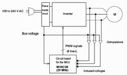
Figure 1 Three-phase motor drive

Figure 2 Motor control hardware block diagram
Inverter control power (commercial power supply) is generally provided through a power supply system. In this case, the voltage, frequency and phase of the commercial power supply are fixed at a precise level under strict control. If a commercial power supply is directly provided to the load of the motor, the induction motor (IM) can be started, while the synchronous motor (such as PMSM) cannot be started.
In the inverter control process, the commercial power supply is not connected to the load. A conversion device first converts alternating current (AC) current into direct current (DC) power, and then an inverter converts the direct current power into alternating current power so as to deliver AC power with a desired voltage and frequency to the motor. If the output voltage and frequency are controlled according to the load and disturbance, this will enable the synchronous motor to start and rotate, and achieve the effect of energy saving.

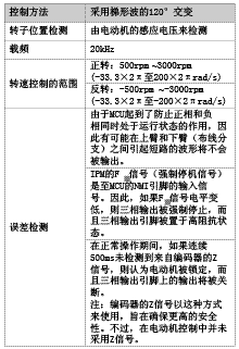
Table 1 Control method 
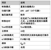
Table 2 A / D conversion

Table 3 Interrupt function
Induction voltage motors can function as generators. Therefore, when a lamp is connected to the motor and the shaft of the motor is rotated, the lamp will emit light. This is because the induced electromotive force is generated, and the generated voltage is called the "induced voltage".
When the motor stops rotating, there will be no induced voltage. Therefore, when the motor is started, it will be forced to rotate in a specific direction to find the position of the rotor.
In the motor control with 180o sine wave alternation, because the current in the motor continuously flows, the induced voltage generated in the motor cannot be directly monitored. Therefore, in the position sensorless control, the rotor position is estimated by the motor current.
Hardware and software specifications for motor control
Hardware Composition Surface Mount Permanent Magnet Synchronous Motor (SPMSM)
A / D converter Three-phase PWM output Zero-point detection of induced voltage The four-part frame diagram is shown in Figure 2.
The software function software control is shown in Table 1.
Function description of CPU and its surrounding equipment for motor control
A / D conversion
A / D conversion instructions are shown in Table 2.
Three-phase PWM output uses sawtooth wave for modulation and three-phase mode 0 to achieve 120o alternating drive motor.
In the 120o alternating with trapezoidal wave, the speed is basically proportional to the voltage.
Zero-crossing detection of induced voltage of three-phase motor In this software, the zero-crossing of induced voltage is detected by configuring the external interrupt function according to Table 3.
Realization of SPMSM sensorless type with trapezoidal wave alternating
The software description of the driver describes how to use the 120o alternating of the trapezoidal wave to realize the sensorless driver of SPMSM. content include:
(1) The rotor position is detected by the induced voltage in the motor and the 120 ° alternating rotation speed with trapezoidal wave is controlled in the range of ± 500 rpm to 3000 rpm.
(2) Description of 8 control modules.
A / D converter Detection of induced voltage Calculation of actual speed Calculation of target speed Calculation of PWN duty cycle Determination of output mode Initial start-up processing Some other CPUs monitor and detect abnormal system actions.
(3) Storage conversion of CPU register
The CPU has 13 registers: data register, address register, frame register, interrupt table register, program pointer register, user stack pointer (USP) register, interrupt stack pointer (ISP) register, status register, flag register (carry flag register, debug flag) Register, 0 flag register, symbol flag register, register group selection flag register, overflow flag register, interrupt enable flag register.) Stack pointer selection flag register, processor interrupt priority register, reserved domain register.
Storage transformations include:
Linear address space, fixed interrupt vector, internal RAM, SFR area, special page vector and other address allocation.
Used for storage transformation and segment configuration of this software
(4) The main software module of the system
(5) Initial setting value of SFR related to three-phase output Setting of control register 0-2 of AD converter Motor induced voltage detection Three-phase output PWM setting (24 registers)
(6) Realization of SPMSM sensorless drive control through 120 ° trapezoidal wave alternating control flow for main process of SPMSM sensorless drive through 120 ° trapezoidal wave initial processing Initialization processing PWM interrupt processing Stop processing Start processing Normal processing Actual rotation speed calculation processing, rotation speed command calculation processing, bus voltage calculation processing, motor lock detection processing, and stop detection processing.
The Work Light is Ideal for mechanic's, DIY, boating, camping, night fishing ,Camping, Hiking, Workshop, Roadside safety, Auto repair, Emergency kits, Survival device, Home security etc.
Both Work Light's Base and Body have strong magnet to magnetize on metal surfaces for more convenience; Use Hook to hang on any place to provide brightness.
The Opereating Time of work light up to 6 Hours As Per One Fully Charged, It can Also be Used as a Backup Battery to Charge Your Phone or Other Digital Device.
Work Light
Work Lights,Extendable Work Light,Rotating Work Light,Switch Light
Ningbo Henglang Import & Export Co.,Ltd , https://www.odistarflashlight.com