One of the key benefits of metal panel capacitive (MoC) touch systems is their high level of sensor flexibility. This means that the sensor design can include hundreds of touch points, and it can maintain a consistent look and feel through various deployment methods. This adaptability makes MoC an excellent choice for a wide range of applications, from industrial controls to consumer electronics.
With so many possibilities, designers need to carefully evaluate different design options to determine which ones best suit their needs. It's essential to understand the advantages and limitations of each approach. That’s why we recommend consulting with a mechanical engineer who has expertise in material properties, manufacturing processes, and how these factors influence performance and durability.
MoC systems are built using Microchip’s mTouch® capacitive sensors along with associated electronics and software. The main difference in MoC design is that instead of a finger, a conductive target layer is placed above the capacitive sensor, separated by a thin spacer. When the user presses the target layer, it deforms slightly—by less than 10 micrometers—which changes the capacitance between the sensor and the target. The capacitive interface then detects this change and reports it to the system.
This configuration isolates the sensor from the environment, significantly reducing issues like noise, proximity interference, and crosstalk. The grounded target layer also provides a safe path for electrostatic discharge, protecting the system from damage. Additionally, the isolation helps prevent water-related problems, making MoC ideal for use in harsh or wet environments. Since the system relies on physical pressure, it works well with Braille interfaces and users wearing gloves.
The professional appearance provided by metal panels adds a premium feel to the final product, making it a popular choice in industries where aesthetics matter as much as functionality.
Sensor System Construction
To build a MoC sensor system, you typically need a standard capacitive sensor, a spacer layer, and a conductive target layer. Figure 1 shows a typical single-layer structure. In this setup, the conductive target layer acts as the second plate of the capacitor and must have enough elasticity to return to its original shape after being pressed.
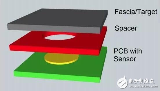
Figure 1: Typical metal panel capacitive sensor stack structure (single layer)
The panel is positioned on top of the laminate and includes markings and button legends. The conductive target layer serves as another conductive surface for the sensing capacitor, providing grounding and mechanical flexibility for the button.
When choosing materials for the panel and target layer, several factors come into play, such as the required pressing force, desired appearance, environmental conditions, backlighting needs, and whether the panel and target layer require illumination. It's often beneficial to integrate the design of both components, as they work closely together during operation.
The simplest implementation involves using a single metal layer as both the panel and the target. For example, printed graphics on the metal surface can act as the panel, while a film applied to the target layer can provide visual feedback. This single-layer design offers all the necessary mechanical resilience and electrical characteristics for the system.
The driving force required to press a button depends on the thickness of the metal, the size of the button, the material's elasticity, and any backside etching. Typically, the size of the button and the material thickness are the most significant factors.
Material selection plays a critical role in determining the performance and longevity of the system. For instance, stainless steel is flexible but not as elastic as aircraft-grade aluminum. On the other hand, aluminum has lower yield strength and may dent under heavy pressure. A balance must be struck between sufficient flexibility for low-force operations and high strength to prevent damage under higher forces.
From an aesthetic perspective, modern screen printing and coating techniques allow for realistic textures, from wood to stone. Metal panels can be electroplated to create detailed markings and custom finishes. Anodized aluminum, for example, can even support photo-quality images, offering a premium look and feel.
Environmental factors such as wear resistance and chemical resistance are also important. Stainless steel is highly resistant to corrosion and common chemicals, making it ideal for long-term use. However, ordinary steel is prone to rust and discoloration. Anodized aluminum provides good wear resistance, but the porous surface must be sealed to prevent corrosion.
Many designers avoid metal panels due to the misconception that they cannot be backlit. In reality, backlighting is possible, though it may cost slightly more than polymer panels. By selectively perforating the metal and using a polymer seal, designers can achieve effective backlighting without compromising performance or aesthetics.
Plastic Panel with Metal Cover
A second common design involves using a plastic panel combined with a metal cover sheet, either screen-printed or vapor-deposited, as the target layer. This method allows the plastic panel to provide the necessary flexibility for the buttons, while the metal layer acts as the ground plate for the capacitive sensor. As shown in Figure 2, this design is simple and effective.
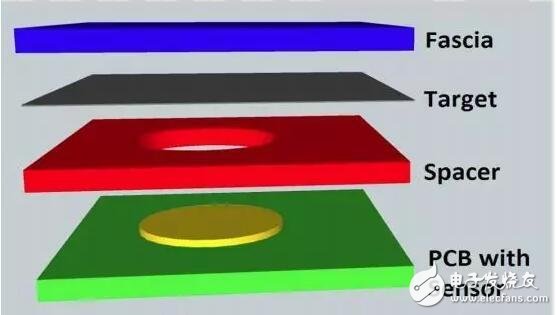
Figure 2: Example of a plastic sensor stack structure
In this configuration, the driving force is influenced by the button size, material thickness, and the degree of back-etching. Thicker materials generally result in higher driving forces. However, plastics tend to be more elastic than metals, allowing for larger panels and target layers without increasing the force needed to activate the button. This also reduces the risk of permanent deformation and dents.
Like metal panels, modern screen printing and coating techniques allow for a wide range of surface finishes on plastic. Metal coatings can be used to create glossy effects and custom markings, enhancing the visual appeal of the design.
One challenge with plastic panels is maintaining optical clarity at higher thicknesses. While polyester can cause transparency issues, this is rarely a problem within standard thickness ranges. Polycarbonate and polyethylene, on the other hand, offer excellent optical clarity. Designers should choose compatible plastic and adhesive combinations to avoid cloudiness or haze.
Although water resistance is less of a concern with plastic panels, wear resistance and chemical resistance remain important. Another factor to consider is the material’s dimensional stability under temperature changes. If the expansion rates of the panel and bonded materials differ significantly, it can lead to adhesive failure, causing false triggers or inconsistent performance.
For markets like food preparation and healthcare, materials must be able to resist microbial contamination. Antimicrobial-coated polycarbonate and polyester are ideal choices for these applications. Additionally, anti-fogging and UV-resistant properties are beneficial if the sensor will be exposed to direct sunlight.
Transparent and translucent plastics are excellent for backlighting. They allow light to pass through, enabling side-lit LED designs for uniform illumination across the entire surface. Even with metal plating, small pinholes can be created via etching to achieve similar lighting effects at a lower cost.
Metal-Plastic Co-Molded Design
The third option involves combining metal and plastic in a co-molded design. A portion of the metal layer is etched or stamped to leave space around the switch, which is then filled with plastic using injection molding. This hybrid approach combines the best qualities of both materials: the wear resistance of metal and the optical properties of plastic.
Figure 3 shows an example of a co-molded panel and target layer. The light gray area represents aluminum, while the dark gray region is the injection-molded plastic surrounding the sensor.
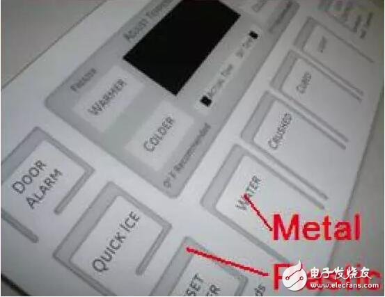
Figure 3: Metal and plastic co-molded panels and target layers
In this design, the driving force is determined by the combined properties of metal and plastic. The actual force is a weighted average based on the geometry of the sensor. The driving force falls between that of a pure metal and a pure plastic design. Estimating the exact value requires understanding the proportions of each material used around the button. By calculating the driving force of similar buttons made from each material and averaging them, designers can get a useful approximation.
The appearance of the sensor is one of the main reasons this design is widely adopted. Metal provides durability, while plastic allows for customization and backlighting. Modern screen printing and coating techniques can replicate the desired look and feel, giving designers greater creative freedom.
However, composite designs introduce additional challenges, particularly in terms of wear resistance, chemical resistance, and material compatibility. The adhesion between metal and plastic must be strong to prevent delamination, especially under extreme temperatures. If the thermal expansion coefficients of the two materials differ significantly, it could lead to structural issues, such as detachment or deformation.
Backlighting in co-molded designs is also more complex, as the plastic component must allow light to pass through the metal. This often requires careful placement of illuminated areas, which may necessitate multiple light sources for optimal visibility.
In conclusion
With these various sensor design techniques, designers have a great deal of flexibility when creating innovative user interfaces. By combining different materials, configurations, and methods, they can develop unique control solutions that are both visually appealing and functionally superior. However, these approaches are not exhaustive. Designers are encouraged to think outside the box and collaborate with creative design service providers to explore new possibilities.
As mentioned earlier, equalization techniques play a crucial role in determining the maximum distance a CoaXPress cable can transmit data at a given rate. To optimize this, Microchip Technology’s 600 MBps CoaXPress chipset uses a dedicated adaptive equalization algorithm to counteract signal degradation caused by cable attenuation. The equalizer estimates frequency-dependent loss and compensates accordingly, ensuring reliable performance over longer distances.
A luminous Solar Inverter is a type of device used in solar power systems that offers additional features beyond those provided by a standard string inverter. The on Off Grid Inverter combines the functions of a traditional solar inverter with a battery charger and can also act as a backup power source during grid outages.
Features
1. Battery Charging: Hybrid inverters have built-in charge controllers that allow them to efficiently charge batteries from the solar panels. This feature enables homeowners to store excess solar energy for use when the sun isn't shining, providing a more reliable and independent power supply.
2. Grid Tying and Islanding: These inverters can operate in both grid-tied mode (feeding excess power back into the grid) and off-grid or islanding mode (powering the home directly from the stored solar energy without connecting to the grid). This versatility allows the system to adapt to different power needs and grid conditions.
3. Energy Management: Hybrid inverters often come equipped with advanced software that allows for sophisticated energy management. This includes the ability to prioritize the use of solar energy, manage battery discharge, and optimize energy usage within the home.
4. Communication Capabilities: Many modern hybrid inverters include Wi-Fi or Bluetooth connectivity, enabling remote monitoring and control of the solar system through smartphone apps or web interfaces.
5. Backup Power: In the event of a power outage, a hybrid inverter can switch over to battery power, ensuring that critical loads continue to be powered even when the grid is down.
6. Efficiency: Hybrid inverters are designed to maximize the efficiency of solar power generation and storage, making them an attractive choice for homeowners looking to reduce their reliance on the grid and lower their electricity bills.
Overall, a hybrid solar inverter provides a comprehensive solution for harnessing and managing solar energy, offering benefits such as increased energy independence, cost savings, and enhanced reliability in power supply.
Luminous Solar Inverter,On Off Grid Inverter,On Grid Off Grid Hybrid Energy Storage Inverter,On Off Grid Hybrid Solar Inverter
Ningbo Taiye Technology Co., Ltd. , https://www.tysolarpower.com