When a mechanical switch is activated, it often produces a phenomenon known as "switch bounce" or "jitter." This can be problematic in sensitive control circuits where stability is essential. To address this issue, a single-pulse generator circuit is commonly used to eliminate the jitter effect caused by mechanical switches.

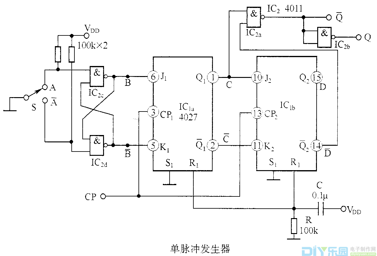
Diagram: Single Pulse Generator
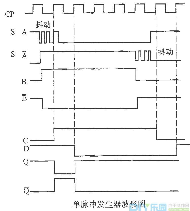
Upon startup, the R and C components reset IC1, setting Q1 and Q2 to 0. The J-K flip-flop IC1 is configured as a 2-bit shift register. When the switch K is set to position 'a,' gate c outputs a '1.' When a CP pulse arrives, Q1 becomes 1. If the switch K experiences jitter, as long as it doesn't remain in the 'a' position, the output of gate c remains at '1.' On the next CP pulse, Q2 also becomes 1. The state transition of Q1 and -Q2 occurs within one CP cycle, and after passing through NAND gate 2a, a single pulse is generated. The waveform of this process is illustrated below.

Waveform: Single Pulse Generator
This circuit ensures that only one clean pulse is generated per switch closure, making it ideal for applications requiring precise timing and signal integrity. Whether in industrial automation, digital electronics, or embedded systems, the single-pulse generator plays a crucial role in improving system reliability and performance.
Copper Clad Steel ,Copper Clad Steel Highly Conductive,Copper Clad Steel Strand,Anti-Oxidation Copper-Clad Stee
changzhou yuzisenhan electronic co.,ltd , https://www.ccs-yzsh.com